
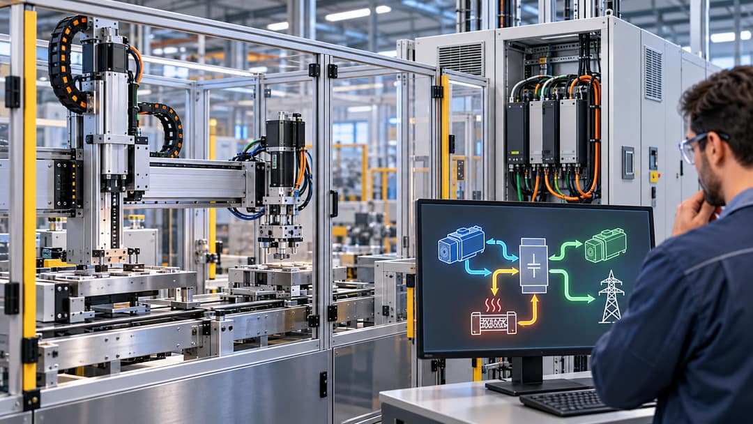
Regenerative servo drives can reduce industrial electricity consumption by recovering energy when motors slow down or when loads drive the motors. However, the amount of energy generated during braking is not necessarily the amount of electricity a factory will save.
Some braking energy is lost through friction and electrical conversion. Some may already be reused by other motors connected to the same drive system. In other installations, braking energy is converted into heat because the equipment cannot return it to the electrical supply.
For manufacturing engineers evaluating regenerative servo drives, the financial question is not simply how frequently a machine brakes. It is how much recoverable energy would otherwise be wasted, where that energy can go, and whether recovering it justifies the equipment investment.
Where Does Servo Braking Energy Go?
A servo motor converts electrical energy into mechanical motion. During certain deceleration or load-driven conditions, the process reverses: mechanical energy drives the motor, which operates as a generator.
The resulting electrical energy enters the servo drive’s DC link, also called the DC bus.
This is the internal electrical connection between the drive’s power-conversion stages. It may also connect multiple drives in a compatible multi-axis system.
The system must then manage the generated energy.
One possible destination is a braking resistor.
A braking resistor converts excess electrical energy into heat. A switching device called a braking chopper connects the resistor when the DC-link voltage reaches a specified threshold.
ABB explains this arrangement in its ACS880 brake-unit technical overview, which describes how braking choppers and resistors manage energy generated by decelerating motors.
Another possibility is to reuse the energy within the machine.
In a compatible multi-axis system, a motor operating in generator mode can supply energy through a shared DC link while another motor is accelerating or driving a load.
This can reduce the electrical energy the machine needs to draw from its supply.
SEW-EURODRIVE describes both shared DC-link energy exchange and regenerative power supply arrangements in its engineering documentation.
The guidance identifies energy exchange between axes and feeding recovered energy back into the supply as separate capabilities.
A third possibility is returning excess energy to the electrical supply.
This requires a suitable regenerative drive or supply unit. Not every servo drive can perform that function.
The distinction matters when comparing products. A drive that can manage braking energy through a resistor is not necessarily capable of returning electricity to the plant’s AC supply.
Manufacturers should confirm the actual drive architecture rather than assume that every product advertised as supporting regenerative braking offers the same energy-saving capabilities.
A Shared DC Bus May Already Be Saving Electricity
Consider an automated packaging machine with several servo-driven axes.
One axis accelerates a product into position while another decelerates after completing its movement.
If the axes share an appropriately designed DC bus, some of the energy generated by the decelerating motor may be used by the accelerating motor.
The machine can therefore reduce its incoming electrical demand without exporting that energy to the wider factory supply.
This creates an important consideration when upgrading equipment.
Suppose engineers install an additional regenerative supply module on a machine that already reuses most of its braking energy internally.
The new equipment may have relatively little excess energy available to export.
The machine may already be capturing much of the practical benefit.
By contrast, a machine with frequent deceleration and substantial resistor braking losses may offer a stronger opportunity for additional energy recovery.
Timing also matters.
When one axis generates energy at the same time another requires it, direct energy exchange may be possible.
If all axes accelerate together and then decelerate together, there may be less opportunity for immediate reuse. Excess energy must be stored temporarily, dissipated, or returned to the supply through suitable equipment.
Beckhoff’s November 14, 2023, description of its AX8820 energy recovery unit provides an example of this engineering approach.
The manufacturer explains that the unit initially allows regenerative energy to remain in the DC link before feeding excess energy back to the grid. Its diagnostic capabilities can also help engineers examine motion timing and opportunities for improved energy management.
This is manufacturer documentation describing a particular product’s capabilities, not independent evidence of savings in an unspecified factory.
The broader lesson is that the operating relationship between axes may matter as much as the choice of regenerative equipment.
How Much Energy Is Available From a Decelerating Axis?
The kinetic energy stored in rotating machinery depends on its rotational inertia and speed.
For a simplified rotating system:
Kinetic energy = ½ × inertia × angular velocity²
Inertia is expressed in kilogram-square meters (kg·m²), while angular velocity is expressed in radians per second.
This relationship provides an initial estimate of the mechanical energy associated with a rotating load.
Consider a hypothetical servo-driven mechanism with an equivalent rotating inertia of 1.2 kg·m².
Assume it decelerates from 1,200 revolutions per minute to rest.
At 1,200 rpm, its angular velocity is approximately 125.66 radians per second.
The initial kinetic energy is:
0.5 × 1.2 × 125.66²
That equals approximately 9,475 joules per stopping event, or 9.5 kilojoules.
Now suppose the mechanism completes 9,600 comparable deceleration events during a production day.
The total kinetic energy associated with those events is approximately:
9,475 × 9,600 = 90,960,000 joules
After converting joules into kilowatt-hours:
90,960,000 ÷ 3,600,000 = 25.3 kWh per production day
This is a theoretical mechanical-energy estimate, not measured electricity recovery.
It does not establish that 25.3 kWh can actually be returned to the plant supply.
Mechanical friction, equipment efficiency, other applied loads, and the way the system brakes will influence the available electrical energy.
For illustration, suppose a suitable regenerative arrangement could deliver a net usable recovery equal to 70% of the calculated kinetic energy.
That 70% figure is a hypothetical assumption, not a manufacturer specification or verified recovery rate.
The resulting estimate would be:
25.3 × 0.70 = 17.7 kWh per day
If comparable operation occurs on 250 days annually:
17.7 × 250 = approximately 4,420 kWh annually
At an assumed electricity value of $0.15 per kWh, that represents approximately $663 per year.
Every input in this example is hypothetical.
The estimated benefit also assumes the recovered energy replaces electricity that would otherwise have been purchased. If the existing equipment already reuses some braking energy, the additional benefit of a retrofit would be smaller.
The example illustrates why impressive motor-speed and braking figures do not automatically establish an attractive investment.
Even a machine with frequent deceleration may have a relatively limited amount of recoverable annual electrical energy.
Peak Braking Power Is Not the Same as Annual Energy Recovery
Another common source of confusion is the difference between power and energy.
Power, measured in kilowatts, describes how quickly energy is transferred.
Energy, measured in kilowatt-hours, describes the total amount transferred over time.
A machine may generate a relatively high level of electrical power during a short braking event.
But if that event lasts only a fraction of a second, the amount of energy involved may be small.
This distinction affects equipment selection.
A regenerative unit must be able to handle the relevant instantaneous braking power. It must also operate within its permitted continuous and intermittent ratings.
SEW-EURODRIVE’s July 2025 technical documentation on determining braking power illustrates how allowable braking power depends on the operating duty cycle.
The documentation also explains that its specified regenerative arrangement requires a suitable supply for energy recovery. During a supply failure, that recovery function is unavailable.
These limitations cannot be ignored when designing machinery.
A system might require equipment capable of handling large short-duration energy flows even though its total annual recoverable energy is modest.
The electrical and mechanical design must also address appropriate stopping behavior when normal power or energy recovery becomes unavailable.
A regenerative drive is not automatically a safety-rated braking system. Emergency stopping, protective controls, load holding, and hazardous-energy management require separate professional assessment.
Engineers should follow applicable machinery safety requirements and the instructions for the specific drive, motor, and machine.
Four Questions That Determine Whether a Retrofit Makes Sense
A useful regenerative-drive evaluation should begin with the machine’s actual operating behavior.
First, how much energy is currently being dissipated?
Manufacturers should identify whether the existing machine uses braking resistors and determine how much energy those resistors dissipate during representative operation.
Resistor temperature alone cannot establish annual energy consumption. Appropriate electrical measurements or validated engineering calculations are needed.
Second, how much energy is already reused?
Multi-axis equipment may already exchange energy through a common DC bus.
Engineers should distinguish energy generated by an axis from energy that remains available for additional recovery after existing reuse.
Third, how often do the relevant operating conditions occur?
The assessment should reflect actual production cycles, machine speeds, loads, and annual operating hours.
A machine that runs continuously under one operating profile may have a very different recovery opportunity from equipment that frequently changes products or operates intermittently.
Fourth, what changes when new equipment is installed?
The proposed installation may require drive replacement, electrical modifications, controls integration, commissioning, and additional engineering work.
These costs must be compared with the incremental value of the electricity recovered.
Mengo Industrial’s existing guide to motion control and servo sizing provides related context for understanding how inertia, torque, motion profiles, and duty cycles affect servo-system selection.
Those same characteristics influence how much mechanical energy is available during deceleration.
Why Recovered Electricity Must Be Measured Correctly
A drive monitoring system may report regenerative power or accumulated regenerative energy.
These readings can help engineers understand machine behavior, but they must be interpreted carefully.
Energy flowing from a motor into a DC bus is not necessarily equivalent to energy returned to the building’s AC supply.
Some may be reused by another motor. Some may remain briefly stored in DC-link capacitors. Some may be lost through power-conversion processes.
For an investment assessment, the most useful measurement is the change in net purchased electricity under comparable operating conditions.
Engineers should establish a reliable baseline before the retrofit and measure performance after commissioning.
The comparison should account for production volume, motion profiles, operating hours, equipment configuration, and any changes to other electrical loads.
For equipment capable of feeding energy back into the plant supply, suitable metering should distinguish incoming and outgoing energy where that information is relevant.
The value of recovered electricity depends on how the site’s electrical system and tariff account for it.
Energy reused immediately by other plant equipment may reduce purchased electricity. Energy exported beyond the facility boundary may be treated differently, depending on the utility arrangements and applicable rules.
Manufacturers should not assume that every exported kilowatt-hour receives the retail electricity price.
The evaluation should also examine potential secondary benefits.
Replacing resistor braking with suitable energy recovery can reduce heat released into an equipment enclosure or electrical room.
That may reduce cooling requirements in some installations, but the benefit must be measured or estimated using an appropriate thermal model.
It should not be automatically counted as an additional saving equal to the recovered electrical energy.
The overall investment analysis should incorporate these considerations alongside equipment cost, maintenance requirements, expected service life, and financial uncertainty.
The site’s custom-equipment budgeting and ROI guide provides a broader framework for evaluating machinery investments rather than relying on a single attractive operating-cost estimate.
When Regenerative Servo Drives Offer the Strongest Business Case
Regenerative equipment generally deserves closer evaluation when machinery repeatedly converts substantial mechanical energy into electrical energy that would otherwise be dissipated.
Potential applications include industrial lifting systems, cyclic motion equipment, test benches, and multi-axis machinery with suitable operating profiles.
However, application type alone does not prove that a regenerative retrofit is worthwhile.
A lift with frequent lowering cycles may have meaningful energy-recovery potential, but its actual benefits depend on load conditions, mechanical losses, operating hours, drive design, and existing electrical infrastructure.
Likewise, an automated assembly machine with many servo axes may already share braking energy efficiently.
The better investment could involve improving motion coordination rather than adding equipment to export energy.
In other situations, existing braking-resistor losses may be so small that a regenerative upgrade produces an unattractive financial return.
These outcomes should be evaluated through the same engineering process: establish the baseline, model realistic operation, check equipment ratings and safety requirements, and estimate incremental net electrical savings.
The final decision should account for total installation cost rather than comparing equipment prices alone.
The Better Metric Is Net Electricity Saved
Regenerative servo technology can improve industrial energy efficiency, but braking frequency and recovered motor energy do not tell the complete story.
Manufacturers need to distinguish the energy generated during deceleration, the energy already reused within the machine, the energy that could be returned to the electrical supply, and the electricity that would actually be avoided.
Those quantities are related, but they are not interchangeable.
The most credible business case combines a representative motion-duty analysis with verified drive specifications, electrical measurements, and a realistic estimate of installation costs.
A successful regenerative-drive project is not defined by how much braking energy the motor generates. It is defined by how much additional purchased electricity the completed system avoids while maintaining the required production and safety performance.


