
Let’s cut through the hype. Building an automation system isn’t about choosing the flashiest arm and crossing your fingers.
It’s more like conducting a symphony where mechanics, electronics, and code must play in perfect, ruthless harmony. One wrong note in your selection process isn’t just a delay. It’s a costly lesson in physics, paid for in scrap metal and downtime.
This guide is your map through that intellectual minefield. We’re moving past the glossy sales brochures and into the gritty, analytical heart of the matter.
We’ll talk about making trade-offs that don’t come back to haunt you. We’ll focus on simulating failures before they’re real. And we’ll engineer safety that’s robust, not just compliant.
Think of it as a pre-mortem for your automation ambitions. Ready to begin?
Application Scoping: takt, payload, reach, workspace, precision
Think of application scoping as the prenuptial agreement for your robotics marriage. It’s where you define exactly what you’re getting into before saying ‘I do’ to a robot. This phase separates the professionals from the amateurs.
Process mapping comes first, not robot selection. I’ve seen too many projects fail because someone fell in love with a shiny arm before understanding their actual needs. Target cycle time isn’t a suggestion—it’s the heartbeat of your operation.
What’s your real takt time? Is it the hard number from the production line, or management’s hopeful wish? Be brutally honest here. Throughput requirements dictate everything that follows.
Consider your product mix today and likely future variants. That “maybe we’ll handle heavier parts next year” thought? Write it down. It matters more than you think for proper robot selection.
Part presentation method determines your dance floor. Quality checks required add steps to your routine. Changeover expectations? That’s your intermission timing.
Defining payload isn’t just part weight. It’s the tool, the inertia, and yes, that secret desire for future flexibility. Reach and workspace planning is spatial chess at industrial scale.
You’re not just fitting a robot in a corner. You’re plotting paths that avoid collisions while allowing maintenance access. Things break, my friends. Leave room for that future vision system you’ll inevitably need.
Precision requires precise definition. Is it repeatability for pick-and-place, or absolute accuracy for machining? The spec sheet won’t tell you what “precision” means for your specific task. Only proper scoping will.
Getting this right makes the difference between a cell that hums and one that stumbles. It’s the foundation of intelligent robot selection. Scope creep gets assassinated here, before it can sabotage your project.
| Scoping Parameter | What It Really Means | Common Pitfalls | Questions to Ask |
|---|---|---|---|
| Takt Time | The heartbeat rhythm your cell must maintain to match production demand | Using optimistic projections instead of actual line data | What’s the hard requirement vs. nice-to-have? How does this sync with upstream/downstream processes? |
| Payload | Total moving mass: part + end effector + any fixtures, plus consideration for dynamic forces | Forgetting tool weight and inertia; ignoring future product plans | What’s the maximum mass we’ll handle in 3 years? How does acceleration affect effective load? |
| Reach & Workspace | The 3D chessboard where your robot operates, including maintenance access zones | Planning only for the robot, not for human access or future equipment | Where will technicians stand during maintenance? What collision zones exist? Can we reach all required positions? |
| Precision | Task-specific accuracy: repeatability vs. absolute positioning vs. path following | Quoting manufacturer specs without understanding task requirements | What tolerance does our process actually need? Is it about returning to the same spot or hitting an exact coordinate? |
This table isn’t just a checklist. It’s your interrogation guide for that brutally honest conversation with your process. Notice how each parameter connects to others? Payload affects precision. Workspace constraints influence takt time.
Future variants deserve special attention. That “maybe” becomes expensive when you need a completely new cell in two years. Document every assumption, including the quiet ones everyone’s thinking but no one’s saying.
Changeover expectations determine your flexibility. Quick product switches need different planning than dedicated runs. Quality checks add time but prevent disasters.
Application scoping done right feels like overkill. Until installation day, when everything just… fits. That’s when you realize this wasn’t paperwork. It was architecture.
FAQ
Q: What is the role of End of Arm (EOA) components in robotics?
A: End of Arm (EOA) components are essential in robotics as they enable the precise and efficient execution of tasks. These components include grippers, sensors, and actuators, which work together to enhance the performance and versatility of robotic systems.
Q: How do grippers contribute to robotic efficiency?
A: Grippers play a vital role in robotic efficiency by providing the necessary functionality to grasp and manipulate objects. They come in various types, such as pneumatic, vacuum, and electric grippers, each designed to handle specific tasks and materials.
Q: What are the different types of grippers available?
A: There are several types of grippers available, including pneumatic grippers, vacuum grippers, electric grippers, and custom grippers. Each type has its own advantages and is suited for specific applications, such as handling delicate materials or heavy objects.
Q: How do sensors contribute to robotic precision?
A: Sensors play a critical role in robotic precision by providing real-time feedback and data to the robotic system. They enable the robot to accurately detect and respond to its environment, ensuring precise and reliable performance.
Q: What are the different types of sensors used in robotics?
A: There are various types of sensors used in robotics, including vision sensors, force sensors, and tactile sensors. Each type of sensor offers unique capabilities and is designed to address specific needs, such as object recognition or force measurement.
Q: How do actuators contribute to robotic efficiency?
A: Actuators are responsible for converting energy into motion within the robotic system. They play a vital role in robotic efficiency by enabling the robot to perform precise and controlled movements, ensuring accurate and reliable performance.
Q: What are the different types of actuators used in robotics?
A: There are several types of actuators used in robotics, including electric actuators, pneumatic actuators, and hydraulic actuators. Each type has its own advantages and is suited for specific applications, such as high-speed movements or heavy-duty tasks.
Q: How do End of Arm (EOA) components contribute to robotic efficiency?
A: End of Arm (EOA) components, including grippers, sensors, and actuators, work together to enhance the performance and versatility of robotic systems. They enable the robot to execute tasks with precision, accuracy, and reliability, contributing to overall robotic efficiency.
EOAT/End Effector: grippers, compliance, quick-change, vacuum design
The end-of-arm tooling is where your robot program meets the real world. It’s like the robot’s personality—its hands, tools, and purpose. Choosing the right EOAT is more than just picking accessories; it’s defining the mission.
This interface affects your cycle time more than any code. A clumsy gripper adds seconds as it tries to grab. A misaligned vacuum cup means a dropped part and a stop. Get it wrong, and your robot becomes slow and thoughtful.
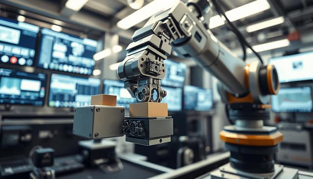
Let’s look at the four key parts of smart end-effector design. First, grippers. The classic two-finger gripper is common, but not always the best. For delicate items, you might need a three-finger gripper. For odd shapes, a soft gripper that molds to the item is best. The goal is to grab securely and quickly.
Second, compliance. This isn’t just for fragile items; it’s a shock absorber. A compliant wrist or force-torque sensor helps the tool adjust. Without it, small misalignments can cause big problems.
Third, quick-change systems. In flexible manufacturing, changing tools quickly is key. Manually swapping tools takes 30 minutes. A quick-change system does it in 30 seconds. This makes your robot versatile and fast.
The fourth pillar is vacuum design. It seems simple—suck and lift. But the physics are tricky. The right cup size and material are important. They affect your throughput and cycle time.
So, how do you choose? Don’t pick the coolest tool first. Start with the part. Analyze its shape, weight, and handling speed. Then choose the tool that can handle it well and fast. Your EOAT is critical. Design it wisely for better production line efficiency.
Motion & Cycle Time: path planning, accel/jerk limits, bottlenecks
In the world of industrial automation, motion planning is key. It decides if your cell performs well or stumbles. It’s not just about speed, but about graceful, intelligent movement that keeps things running smoothly.
Start with the path. A direct, optimized robot path is the shortest way to your goals. Place pick and place positions to cut down travel and avoid unnecessary moves. Think of it as GPS for your robot—every detour costs money.
Now, let’s talk physics. You can set fast speeds, but if your acceleration and jerk limits are off, you’ll damage things. Jerk—the rate of change of acceleration—is critical. Too high, and you’ll shake everything loose. Too low, and your cycle time will suffer. Finding the right balance requires knowing your payload and how much vibration it can handle. For more on smooth motion, check out jerk-controlled trajectory planning.
The robot’s motion is often not the main bottleneck. The real cycle time killers hide in plain sight.
Is your part presentation consistent? If parts arrive unpredictably, your robot waits. Each hesitation, retry, and moment of uncertainty adds up. These seconds quietly reduce your throughput. The data shows that cycle time is often lost before the robot even moves.
Then there’s the handshake. Is the communication between your robot and the machine tool quick or slow? A small delay in I/O response can add up over thousands of cycles. Suddenly, you’re losing hours.
The optimization mindset shifts here. It’s not just about making the robot faster. It’s about ensuring it never has to wait. Eliminate pauses, streamline handoffs, and smooth transitions. Your goal is a perfectly choreographed production where everyone hits their mark on time.
Watch these hidden inefficiencies closely. That’s where you’ll find the real seconds—and dollars—waiting to be reclaimed.
Safety: risk assessment, fencing, scanners, PL/CL, cobot force limits (ISO/TS 15066)
The difference between a safe robot cell and a dangerous one isn’t the hardware—it’s the ability to foresee failure. Safety engineering is key to a strong system. It’s not just about checking boxes. It’s about creating layers of defense to make accidents unlikely.
Let’s begin with the basics: risk assessment. This isn’t just paperwork. It’s a detailed look at every possible “what if.” What if a part flies out of the gripper? What if a maintenance tech leans in at the wrong moment? What if a sensor fails?
After identifying risks, you build your defenses. Physical barriers are the first line of defense. Fixed fencing acts as a perimeter wall. It clearly shows the rule: don’t enter when the robot is moving.
But sometimes, access is needed. That’s where digital barriers come in. Light curtains and safety scanners create invisible walls. Break the beam, and everything stops. These aren’t just sensors. They’re your first line of defense against human mistakes.
Now, let’s talk about the control system’s brain. This is where Performance Levels (PL) and Categories (CL) come into play. Think of PL as how reliable your safety system needs to be. Category defines how it’s built—with redundancy, monitoring, or simple components.
A higher PL means a lower chance of dangerous failure. It’s engineering speak for “we really, really don’t want this to fail.” Getting this right isn’t optional. It’s the heart of ISO 10218, the safety standard for industrial robots.
| Safety Measure | Primary Function | Best For | Key Standard Reference |
|---|---|---|---|
| Fixed Guarding (Fencing) | Physical separation, prevents access | High-speed, high-risk zones | ISO 10218-2 |
| Light Curtains & Scanners | Presence detection, stops motion on intrusion | Areas needing occasional access | ISO 13855 |
| Emergency Stop Systems | Manual initiation of safe stop | All robot cells, required access points | ISO 13850 |
| Collaborative Operation | Shared workspace with force/power limiting | Cobot applications, human-robot teams | ISO/TS 15066 |
Collaborative robots change the game entirely. With cobots, the fence often comes down. Humans and robots work side-by-side. This requires a different rulebook: ISO/TS 15066.
This technical specification isn’t a suggestion. It’s the definitive guide for safe collaboration. It defines precise limits—how much force a cobot can apply, how much pressure it can exert. These numbers prevent a helpful robot from becoming a hazard during unexpected contact.
The magic of ISO/TS 15066 is in its quantification. It doesn’t just say “be safe.” It says “28 Newton maximum for transient contact on the arm” and “140 Newton maximum for quasi-static contact.” This turns safety from philosophy into physics.
Here’s the sage advice: use simulation to test your safety logic. Before you trust a system with human lives, drive it through thousands of virtual edge cases in simulation. Test power loss scenarios. Test sensor failures. Test what happens when someone drops a tool in the wrong place.
Simulation lets you prove your safety design works in the digital world. You can validate interlock logic, zone monitoring, and safe stop behavior without ever exposing anyone to risk. It’s the ultimate safety sandbox.
Good safety design following ISO 10218 principles doesn’t slow you down. It ensures you never have to stop for the wrong reasons. It’s the engineering that lets innovation happen without the ambulance ride. Build your layers well, and your robot cell becomes not just productive, but predictably, reliably safe.
Vision-Guided Robotics: 2D/3D picking, calibration, lighting
Teaching a robot to see is like giving glasses to a philosopher—suddenly, the abstract becomes tangible. Vision systems are the robot’s interpreter for our messy, unpredictable world. They bridge the gap between digital precision and physical chaos.
Think of 2D picking as reading a well-organized book. Parts lie flat on a conveyor, nicely contrasted against a known background. It’s orderly, predictable. 3D picking, on the other hand, is like interpreting abstract art. You’re dealing with bin picking, unordered piles, and parts at crazy angles. This is a computational heavy lift, requiring serious processing power.
Here’s where your earlier decisions on reach and payload get a reality check. That camera and its lighting rig aren’t weightless. Mount them on the end-of-arm tooling, and you’ve added to your payload. The robot might need to maneuver to a specific “look” position, eating into your precious reach envelope and stretching cycle times.
Calibration is the unglamorous, critical backstage work. It aligns the robot’s coordinate world with the camera’s pixel world. Get this math wrong, and your million-dollar cell has the precision of a drunk dart player. It’s the handshake between mechanics and optics.
Lighting? It’s everything. Bad lighting creates shadows, glare, and optical confusion. Your sophisticated vision system becomes as useful as sunglasses at midnight. This is where simulation shows its genius.
Modern robotics simulators can produce photorealistic frames, depth maps, and point clouds. You can study glare, motion blur, even rain drops on optics in a controlled, digital sandbox. Want to test mixed lighting from factory windows and overhead LEDs? Simulate it first. This synthetic data lets you stress-test your vision design before cutting metal.
Designing a vision-guided cell means thinking in interconnected layers. Mechanics, kinematics, optics, and processing must work in concert. It’s not just about the robot’s arm anymore. It’s about creating a perceptive system that understands its environment.
The camera’s placement directly influences the arm’s required reach. The lighting system’s weight contributes to the total payload. Every optical decision has a mechanical consequence. This integration separates basic automation from intelligent robotics.
Utilities & Layout: cable dress, air, vacuum, maintenance access
Cable management in robotics is not just about keeping things tidy. It’s about avoiding digital disasters. The backstage work ensures the robot’s performance doesn’t end in a mess. This is where engineering meets art.
Think of cable dress as the robot’s nervous system. A snagged cable can cause sudden failure. It’s not about looks; it’s about keeping signals and power flowing.
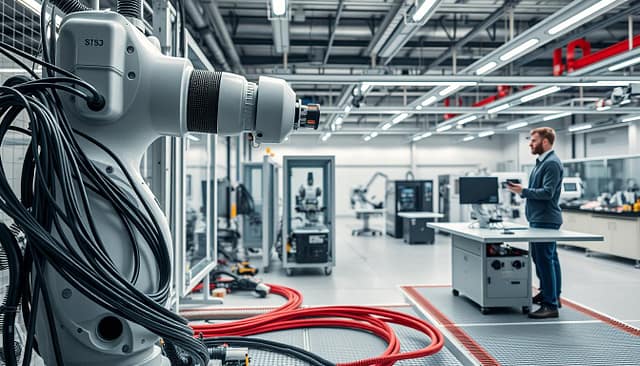
Air and vacuum systems are essential, not just extras. Pneumatic grippers and vacuum cups need clean air and suction. Keeping these systems accessible is key to avoiding downtime.
The cell’s physical structure is also critical. We make robot pedestals and frames ourselves. A stable base is essential for precision.
Guard design is about more than safety. It’s about creating clear paths and access doors. Good design can save a lot of time during repairs.
Maintenance access is a top priority. If repairs are hard, your layout needs work. The best layouts make maintenance easy and safe.
A well-designed robotics cell is a sight to behold. Everything is in its place, and maintenance is a breeze. The right setup lets the robot work smoothly, day after day.
Commissioning: TCP calibration, payload ID, mastering
Commissioning is like the opening night of your robotic show. All rehearsals are done, and now it’s time to start. It’s where digital plans meet real metal, and many projects lose steam here.
Production managers are watching the clock, and floor space is expensive. If the robot doesn’t work as expected, it’s stressful. But, the smartest moves are made before stepping onto the floor.
Let’s look at the three key steps of commissioning. First, TCP calibration sets the end effector’s exact location in space. If this is wrong, your robot’s precision is off.
Then, payload identification tells the robot what it’s lifting. It’s about smooth moves, not just strength. This prevents the robot from wobbling.
Lastly, mastering helps the robot remember its position after a reset. It’s like muscle memory for robots. Without it, the robot acts like it has amnesia.
Most teams make a big mistake here. They try to do all these steps live on the floor. It’s like tuning a race car during the race.
The smart thing to do is do 90% of the work offline. Use your digital twin to plan and test. Premier Automation shows this with their offline tools.
This way, commissioning on-site is just fine-tuning. You arrive with most issues solved. Your checklist gets shorter.
- Verify TCP calibration against physical reference points
- Confirm payload parameters match actual tooling weight
- Execute mastering procedure and validate positional accuracy
- Run through critical path sequences for final timing checks
This makes commissioning faster and less disruptive. You’re making small tweaks, not fixing big problems. You show off your robot’s skills, not delays.
Commissioning is about confirming solutions, not finding problems. Your digital twin should have shown you any issues. Now, you just make sure it works in real life.
This method makes commissioning predictable and controlled. You know it will work, not just hope. This is the difference between a smooth start and a learning experience.
Performance Monitoring: KPIs, predictive maintenance hooks
Your robotics cell is live. Commissioning is done. Now, it’s time to optimize and look ahead. It’s like moving from setting up the stage to directing the show.
Set your Key Performance Indicators with great care. Look at cycle time, uptime, mean time between failures, and quality yield. These are not just numbers; they show how well your production is doing.
Modern control systems from Siemens or Rockwell Automation give you lots of data. Use logging frameworks to mark each run with details. Keep records of motion, perception, and compute load like a digital diary.
Analysis scripts are your diagnostic tools. They check error bands, settling times, contact forces, and latency. They turn raw data into useful information. Is a KUKA joint motor getting too hot over time? That’s a sign of trouble ahead.
Make dashboards that tell stories, not just show numbers. Give your Fanuc or ABB robot a voice. When vibration patterns change, it means something about the bearings. When cycle times start to slip, it shows the process is getting tired.
This changes how you do maintenance. You go from fixing things after they break to fixing them before they break. Your cell becomes more than just a machine; it becomes a smart production asset.
Performance monitoring is the final step in making your robot top-notch. It’s where engineering meets economics, where investment meets return. Your robot isn’t just working; it’s getting better and better.


